---
title: Verilog By Example
h1: Verilog By Example
description: Verilog tutorial covering installation through creation of RTL and Memories, simulation and viewing waveforms.
author: JWRR
date: January 11, 2019
...
![Picture of ASIC](img/jwrr-asic.jpg)

<div class="intro">
[View markdown](verilog-by-example.md)
## The Underworld of Digital Design

> Abandon all hope, ye who enter here. -
> [Dante](https://www.gutenberg.org/files/1001/1001-h/1001-h.htm)

Perhaps that''s too dark. I prefer
["Hope springs eternal" - A. Pope](https://www.gutenberg.org/files/2428/2428-h/2428-h.htm)
as I have survived this world of Digital Design for a score and more years.
I''ve worked on FPGAs and designed ASICs. I''ve written more than a
line or two of Verilog and VHDL.  If I, of all people, can survive, nay...
thrive, then you definitely can.

This post is a brief introduction to the very cool Verilog Hardware Description
Language.  Verilog is the domininate language of digital design.  Well,
[there is another](https://www.youtube.com/watch?v=sLlu_RpElBs)... but
let''s not go there now.

Hopefully this post provides enough Verilog goodness to get you started in the
right direction. Best of luck and welcome to the exciting world of ASIC and
FPGA design.

On the job I use expensive commercial tools. I will use freely available tools
in this post.
</div>

{{ toc }}

##@ Install Verilog on Ubuntu 18.04 Bionic

```
sudo apt-get update
sudo apt-get install gplcver
```

Free, open-source Verilog simulators are:

* [GPL Cver](https://sourceforge.net/projects/gplcver) - Excellent Verilog
  Simulator
* [Verilator](https://www.veripool.org/wiki/verilator) - Blazingly Fast
  simulator used on many commercial products
* [Icarus Verilog](http://iverilog.icarus.com/) - Highly recommended simulator

Other free Verilog simulators are:

* [ModelSim PE Student Edition](https://www.mentor.com/company/higher_ed/modelsim-student-edition)
  Professional quality HDL simulator
* [Xilinx Vivado WebPACK](https://www.xilinx.com/products/design-tools/vivado/vivado-webpack.html)
  Xilinx FPGA tools including Vivado HDL simulator
* [Quartus II Web Edition](https://www.intel.com/content/www/us/en/programmable/downloads/software/quartus-ii-we/120.html)
  Altera (now Intel) FPGA tools including HDL simulator

##@ Installation on CentOS

```
su
yum install gplcver
which cver
exit
cver helloworld.v
```

##@ Hello World

Create a simple Hello world verilog program

```
module helloworld;
  initial begin
    $display("hello from verilog!");
  end
endmodule
```

A Verilog module is similar to a Java/C++ object. It starts and ends with the
keywords **module** and **endmodule**, respectively.

A Verilog **initial** block is similar to **main** in Java/C.\
An initial
block starts when the simulation starts and it stops when it gets to the end.
A Verilog program can have multiple initial blocks, each running concurrently,
similar to multiple threads.

Verilog uses **begin** and **end** instead of the curly braces **{** and **}**.
Similar to C/Java, if there is only one statement in a block then the
begin/end are optional. The above example's 3-line initial block could have
been this one-liner:

```
  initial $display("hello from verilog!");
```

The **$display** statement is similar to printf, with a format
string followed by a list of things to print.

With those few lines you're ready to run your first Verilog simulation.
To run using [cver](http://sourceforge.net/projects/gplcver/) type this on
the command line:

```
cver helloworld.v
.
output:
hello from verilog!
```

Welcome to the world of digital hardware design and verification.

##@ Data Types

```
module verilog_types;
  reg        one_bit;
  reg [1:0]  two_bits;
  reg [7:0]  byte_8bits;
  reg [15:0] two_bytes;
  reg [31:0] thirty_two_bit_word;
.
  integer    i1,i2,i3;
.
  initial begin
    one_bit  = 1'b0;
    two_bits = 2'd2;
    byte_8bits = 8'ha5;
    two_bytes = {5'h0,one_bit,two_bits,byte};
    thirty_two_bit_word = 32'habcdef02;
    $display("one_bit = %b, two_bits = %b, byte = %d, two_bytes = %h thirty_two_bit_word = %h",
             one_bit,two_bits,byte,two_bytes,thirty_two_bit_word);
  end
endmodule
.
output:
one_bit = 0, two_bits = 10, byte = 165, two_bytes = 02a5 thirty_two_bit_word = abcdef02
```

Don't let the name fool you, a **reg** is not a flip-flop register.
For now just think of it as a variable. It can be given any bit width
using the format **reg [msb:lsb] name**. You can also use  **[lsb:msb]**,
but it is not common practice.

An **integer** is a 32-bit value. I almost always use **reg [31:0]** instead of
integer (even for 32-bit values: **reg [31:0] ii;**). I only use integers
as loop counters.

In Verilog a **constant** consists of a bit-width, a radix and a value
(**width'radixvalue**). The width is optional but recommended. The radix
(b=binary, o=octal, d=decimal, h=hex) defaults to decimal if omitted.  If the
width is specified then the radix is require (**8'd12** is valid, but **8'12**
is not). If the width is not specified and the radix is specified then a
leading tick is needed (**'haa or 'b1010** are valid, but **haa** or **b1010**
are not). If the width and radix are not specified then only the decimal value
is needed (**1234** is a valid decimal representation of one thousand two
hundred thirty four).

Verilog uses the curly braces for **bit concatenation**. It's pretty flexible
as shown in the example above.

##@ Bit Width Mismatches
When a smaller (few bits) reg is assigned to a
larger (more bits) reg (for example: **larger[15:0] = smaller[7:0];**),
Verilog automatically increases the size of the smaller register
(**larger[15:0] = {8'h0,smaller[7:0]};**). This zero-fill is usually
the right thing to do, but it's not correct when we're working with
[signed numbers](#signed-numbers-in-verilog).

When a larger register is assigned to a smaller register
(**smaller[7:0] = larger[15:0];**), Verilog will discard the upper,
most-significant bits (**smaller[7:0] = larger[7:0];**), which is almost always
the wrong thing to do. So be careful about bit-widths.


##@ Reg vs Wire
If you've seen some other Verilog, you may have seen some values that are of
type **reg** and others of type **wire**.  Wires are cool, but don't worry
about them for now. I personally think that having both **reg** and **wire**
types was a bad idea. The SystemVerilog team may agree because they've added
yet another type called **logic** which and be used as either a **reg** or as
a **wire**.

The following code show examples of flow control in Verilog.

```
module verilog_flow_control;
  integer i;
.
  initial begin
&nbsp;&nbsp;&nbsp;&nbsp;for (i=0; i&lt;4; i=i+1) begin
&nbsp;&nbsp;&nbsp;&nbsp;  $display("in for loop i = %d",i);
&nbsp;&nbsp;&nbsp;&nbsp;end
.
&nbsp;&nbsp;&nbsp;&nbsp;i=0;
&nbsp;&nbsp;&nbsp;&nbsp;while (i&lt;8) begin
&nbsp;&nbsp;&nbsp;&nbsp;  if (i[0]) begin
&nbsp;&nbsp;&nbsp;&nbsp;    $display("in while loop i = %d",i);
&nbsp;&nbsp;&nbsp;&nbsp;  end &sol;&sol; if
&nbsp;&nbsp;&nbsp;&nbsp;  i=i+1;
&nbsp;&nbsp;&nbsp;&nbsp;end &sol;&sol; while
.
&nbsp;&nbsp;&nbsp;&nbsp;repeat (4) $display("in repeat loop");
.
&nbsp;&nbsp;&nbsp;&nbsp;repeat (4) begin
&nbsp;&nbsp;&nbsp;&nbsp;  $display("in repeat loop again");
&nbsp;&nbsp;&nbsp;&nbsp;  $display("in repeat loop another line");
&nbsp;&nbsp;&nbsp;&nbsp;end
.
  end &sol;&sol; initial
endmodule
```

Verilog supports the typical flow control statements, as found in C/Java.
Verilog does not support the **++** incrementer, so **i=i+1** is need
instead of **i++**. The verilog **repeat** is straight-forward, but unique
and different from C/Java.  In the example above the repeat is executed 4
times. In the example above, the first repeat loop has only a single
command (**$display("in repeat loop");**) that is repeated four time.  In
the second repeat loop, a **begin** and **end** encapsulate the multiple
commands repeated in the loop.

##@ Time

Time is an essential part of almost all digital designs.  Verilog provides
the **$time** variable.  I believe **$time** is a 64-bit value, but the
size isn't really important, just know that it's a big, integer value that will
(probably) never overflow.

Let's watch what happens to $time as the program runs.  As you can see from the
output, **$time** stays at time=0 for the entire run, even though many
statements were executed.

Executing Verilog statements does NOT advance time.
```
module verilog_time0;
  integer i;
  initial begin
    for (i=0; i&lt;4; i=i+1) begin
      $display("Time = %t: for-lopp i = %d",$time,i);
    end // for
  end // intial
endmodule
.
output:
Time =                    0: for-lopp i =                    0
Time =                    0: for-lopp i =                    1
Time =                    0: for-lopp i =                    2
Time =                    0: for-lopp i =                    3
```

So in verilog statements do not take any **time** to execute.  The only way to
advance time is to specifically state that you want time to advance. Verilog
uses the pound (#) command to advance time.

Executing the Verilog # command advances time.

```
// `timescale 1 ns / 1 ps
module verilog_time10;
  integer i;
  initial begin
    for (i=0; i&lt;4; i=i+1) begin
      $display("time = %t: for i = %d",$time,i);
      #10;
    end
  end
endmodule
.
output:
Time =                    0: for-lopp i =                    0
Time =                   10: for-lopp i =                    1
Time =                   20: for-lopp i =                    2
Time =                   30: for-lopp i =                    3
```

The **#10** represents 10 generic time units.  I've found generic time units
good enough for almost everything.  Sometimes you need to specify the time
units and Verilog allows this with the **`timescale** preprocessor directive
(it is commented out in the above example). If you do use this directive, then
you'll save yourself some pain by just putting it at the top of the first file
in the compile list.

In the example the **#10;** appears to be a stand-alone command, but it''s
really a clause that is prepended to a command or command block. So in the
example, **#10;** is really **#10 null;**. A (commonly used) time command is
something like **#10 x = 5;**. Since a single command can always be replaced
by a **begin end** block, another (almost never used) alternative
is **#10 begin x = 5; y = 10; end**.

## Units of Time

While on the subject of time, here is a quick table of time units.

<table border="1" cellpadding="5">
<tr><td>ms</td><td>millisecond (10<sup>-3</sup> sec) - 1 thousandth of a second (kiloHertz)</td></tr>
<tr><td>us</td><td>microsecond (10<sup>-6</sup> sec) - 1 millionth of a second (MegaHertz)</td></tr>
<tr><td>ns</td><td>nanosecond (10<sup>-9</sup> sec)  - 1 billionth of a second (GigaHertz) - most logic runs in the ns range</td></tr>
<tr><td>ps</td><td>picosecond (10<sup>-12</sup> sec) - 1 trillionth of a second (TeraHertz)</td></tr>
<tr><td>fs</td><td>femtosecond - fast</td></tr>
</table>

##@ Clocks

Let's use a combination of Verilog's **For-Loop** and **#** to make a 100
MegaHertz (MHz) clock.  Take the reciprocal of 100MHz to get the period, 10
nanoseconds (ns). So the 100MHz clock will have a period of 10ns with a
transition ever 5ns (5ns low, 5ns high...).

```
module verilog_clock;
  integer i;
  reg clk_signal_name_is_not_magic;
  initial begin
    clk_signal_name_is_not_magic = 0;
    for (i=0;i<100;i=i+1) begin
      #5;
      clk_signal_name_is_not_magic = !clk_signal_name_is_not_magic;
      $display("time = %t: clock = %b",$time,clk_signal_name_is_not_magic);
    end
  end
endmodule
.
output:
time =                    5: clock = 1
time =                   10: clock = 0
time =                   15: clock = 1
time =                   20: clock = 0
time =                   25: clock = 1
time =                   30: clock = 0
time =                   35: clock = 1
time =                   40: clock = 0
time =                   45: clock = 1
time =                   50: clock = 0
...
```

##@ Make a Counter Using the Clock

Now that we have a clock, let's make a counter that increments on every rising
edge of the clock. The Verilog **@** causes the execution of commands to stall
and wait for an event before continuing.  On line 18 the event is the rising
edge (**posedge**) of signal **clk**. After the posedge clk event  happens the
code starts running again (the counter increments), until it hits
the **@(posedge clk);**, and then it waits again.

Here are some commonly used variations of the Verilog **@**:

* @(posedge clk) - Wait for the rising edge of the clock. This is very common
  for Flip-Flop (FF) style operation.
* @(negedge clk) - Wait for the falling edge of the clock. Falling edge FFs
  are not as common as rising edge FFs, but they do have their uses.
* @(signalname) - Wait for any transition on signalname. This is usually used
  for combinatorial logic. Verilog-1995 allows you to wait for a transition on
  any signal in a list with the **or** (**@(sig1 or sig2 or sig3)**).
  Verilog-2001 added a simpler syntax to wait for multiple signals
  (**@(sig1,sig2,sig3)**), but for combinatorial logic I recommend using the
  next bullet's format whenever possible.
* @(\*) - Wait for any transition.  This was added in Verilog-2001 and, when
  possible (which is almost always in normal use cases), should be used instead
  of **@(signalname)**. Verilog-2001 also provides a simpler form as
  well: <b>@*</b>, it saves a couple of parentheses.

##@ Sensitivity List

As with the **#**, the **@** is not a stand-alone command but is pre-pended to
a command or command block, so the three forms are:

* @(posedge clk); - In this case the command is <null&gt;
* @(posedge clk) x = 5; - In this case the **@** preceeds a single command.
* @(posedge clk) begin x = 5; y = 10; end - In this **@** preceeds a block of
  commands. This, believe it or not,  is a common use model which we'll see
  when we get to the **always** block, so don't forget this form.

The **sensitivity list** is the list of signals that the **@** waits for. In
the above examples `posedge clk` is the sensitivity list.

Now let's make a counter that uses the clock that we just made.

```
module verilog_using_clock;
  integer clk_cnt;
  reg clk;
  initial begin
    clk = 0;
    for (clk_cnt=0;clk_cnt<100;clk_cnt=clk_cnt+1) begin
      #5;
      clk = !clk;
      // $display("time = %t: clock = %b ",$time,clk);
    end
  end
.
  reg [7:0] counter;
  initial begin
    counter = 0;
    while (1) begin
      @(posedge clk);
      counter = counter + 1;
      $display("time = %t: counter = %d",$time,counter);
    end
  end
endmodule
.
output:
time =                    5: counter =   1
time =                   15: counter =   2
time =                   25: counter =   3
time =                   35: counter =   4
time =                   45: counter =   5
time =                   55: counter =   6
...
```

##@ RAM (Randam Access Memory)

Now let us make a Random Access Memory (RAM). There are many variations on how
a RAM can be implemented. In this example the RAM has inputs **address**,
__write_data__, **enable** and **write** and output **read_data**. When
__enable==1; write==1__ the value of  **write_data** is written into the ram
location selected by **address** **(ram[address] = write_data)**. When
__enable==1; write==0__ the value of the select ram location is driven onto
the **read_data** bus **(read_data = ram[location])**. When **enable==0** the
RAM output stays the same, even if the address changes.

This program consists of three parts, the Clock Generator, the RAM, and the
Test Logic.

The *Clock Generator* is similar to the one previously described.  Just to
demonstrate different styles, the example uses **#5 clk = !clk;** instead
of **#5; clk = !clk;**. The two are functionally identical, use which ever one
makes sense to you.

The *RAM* behaves as described above.  Of particular interest, the *clk* is
shared by all three **initial** blocks, it is generated in the clock block and
used by the RAM and TEST blocks. Similarly, the RAM inputs and output are
shared between the RAM and TEST blocks. This is an important concept. I view
it as each initial block is a thread, and the variables (regs) are shared
between the threads.

The *TEST block* writes to each ram location.  It then reads each ram location
and verifies that the output value **(read_data)** matches the expected value
__(expected_read_data)__.

### Verilog RAM Module

```
module verilog_ram1;
.
  // Clock ===============================
  reg clk; // clk is shared by all blocks
  initial begin
    clk = 0;
    repeat(8000) begin
    #5 clk = !clk;
  end
end // clock initial block
.
  // Registers shared by RAM and TEST blocks
  reg [9:0] address;
  reg [7:0] write_data,read_data;
  reg       enable,write;
.
  // RAM ==================================
  reg [7:0] ram[0:1023];
  initial begin
    while (1) begin
      @(posedge clk);
      if (enable) begin
        if (write)
          ram[address] = write_data;
        else
          read_data = ram[address];
        end // if (enable)
      end // while
    end // ram initial block
.
// TEST ==================================
  integer i;
  reg [7:0] expected_read_data;
  initial begin
    for (i=0;i<1024;i=i+1) begin
      @(posedge clk);
      enable = 1;
      write  = 1;
      address = i;
      write_data = i;
    end
    $display("time = %t: writing done",$time);
    for (i=0;i<1024;i=i+1) begin
      @(posedge clk);
      enable  = 1;
      write   = 0;
      address = i;
      @(posedge clk);
      expected_read_data = i[7:0];
      if (read_data != expected_read_data) begin
        $display("time = %t: actual=0x%x expect=0x%x FAIL",
                 $time,read_data,expected_read_data);
      end
    end
    $display("time = %t: reading done",$time);
  end
endmodule
.
output:
time =                10235: writing done
time =                30715: reading done
```

##@ Always Block (Very Important)

Verilog provides an **initial** block and an **always** block.

As described above, the **initial** block starts running at **$time=0** and it
stops after it reaches the end of the block.  The **always** block also starts
running at $time=0, but when it reaches the end, insteading of stopping, it
re-starts again. So **always begin ... end** is equivalent of **initial
while(1) begin ... end**.

It doesn't seem like a big deal, so why do I call it **Very Important**?
Because the synthesis tools makers say so. The synthesis tools will not convert
anything in an **initial** block into gates.  For any Verilog that you want to
into an FPGA or ASIC  must use the **always** block instead of the **initial**
block. It seems pretty arbitrary, but it is what it is.

Here is a Verilog RAM using **always block**.

```
module verilog_always_block;
.
// Clock ===============================
reg clk;
reg done;  // TEST block sets done=1 to stop test
initial begin
  clk = 0;
  done = 0;
  while (!done) #5 clk = !clk;
end // clock initial block
.
// Registers shared by RAM and TEST blocks
reg [9:0] address;
reg [7:0] write_data,read_data;
reg       enable,write;
.
// RAM ==================================
reg [7:0] ram[0:1023];
always begin
  @(posedge clk);
  if (enable) begin
    if (write)
      ram[address] = write_data;
    else
      read_data = ram[address];
  end // if (enable)
end // ram always block
.
// TEST ==================================
integer i;
reg [7:0] expected_read_data;
initial begin
  for (i=0;i<1024;i=i+1) begin
    @(posedge clk) enable = 1;  // <-- subtle change
    write  = 1;
    address = i;
    write_data = i;
  end
  $display("time = %t: writing done",$time);
  @(posedge clk);
  for (i=0;i<1024;i=i+1) begin
    enable  = 1;
    write   = 0;
    address = i;
    @(posedge clk) begin expected_read_data = i[7:0]; end // <<-- subtle change
    if (read_data != expected_read_data) begin
      $display("time = %t: actual=0x%x expect=0x%x FAIL",
               $time,read_data,expected_read_data);
    end
  end
  $display("time = %t: reading done",$time);
  done = 1; // stops the clock
end
.
endmodule
```

##@ Create and Instantiate a (sub) module

Here we create a new module (module ram). It is created at the top-level, it is
not create inside of the first module (modules can''t contain other module
definitions).

When the module is instantiated, the ports can defined *by order* (similar to
Java/C), or the ports can be defined *by name*.  By name is far more common and
recommended, especially when the module has many ports.  With *by order* it is
easy to mess up the order, and it is often difficult and time-consuming to
debug.

When the module is instantiated the port signals are separated by a comma
(**,**), but there shouldn't be a comma after the last signal (many tools give
a misleading/confusing message for this error).

By convention, each module is in its own file and the filename and the
modulename are the same (module ram is in ram.v).

In module ram I moved the sensitivity list before the **begin** as described in
the [sensitivity list discussion](#sensitivity-list). It is common practice to
place the sensitivity list between the **always** and the **begin**
(**always @(sensitivity_list) begin**).

### Create and instantiate a Verilog RAM

```
module verilog_module;
.
// Clock ===============================
reg clk;
reg done;  // TEST block sets done=1 to stop test
initial begin
  clk = 0;
  done = 0;
  while (!done) #5 clk = !clk;
end // clock initial block
.
// Registers shared by RAM and TEST blocks
reg  [9:0] address;
reg  [7:0] write_data;
wire [7:0] read_data; // <<-- changed from 'reg' to 'wire'
reg        enable,write;
.
// RAM ==================================
// ram u_ram (clk,enable,write,address,write_data,read_data); // <<-- by order
ram u_ram (
  .clk(clk),          // input <<-- by name
  .enable(enable),    // input
  .write(write),      // input
  .address(address),  // input [9:0]
  .write_data(write_data), // input [7:0]
  .read_data(read_data)    // output reg [7:0] <<-- No comma
); // <<-- semicolon
.
// TEST ==================================
integer i;
reg [7:0] expected_read_data;
initial begin
  for (i=0;i<1024;i=i+1) begin
    @(posedge clk) enable = 1;
    write  = 1;
    address = i;
    write_data = i;
  end
  $display("time = %t: writing done",$time);
  @(posedge clk);
  for (i=0;i<1024;i=i+1) begin
    enable  = 1;
    write   = 0;
    address = i;
    @(posedge clk) begin expected_read_data = i[7:0]; end
    if (read_data != expected_read_data) begin
      $display("time = %t: actual=0x%x expect=0x%x FAIL",
               $time,read_data,expected_read_data);
    end
  end
  $display("time = %t: reading done",$time);
  done = 1; // stops the clock
end
.
endmodule // verilog_module
.
.
module ram(
  input clk,
  input enable,
  input write,
  input [9:0] address,
  input [7:0] write_data,
  output reg [7:0] read_data // <<-- No comma
 ); // <<-- semicolon
 reg [7:0] ram[0:1023];
 always  @(posedge clk) begin // <<-- put sensitivity list before begin
   if (enable) begin
     if (write)
       ram[address] = write_data;
     else
       read_data = ram[address];
   end // if (enable)
end // ram always block
.
endmodule // ram
```

##@ Parameters to Make Modules Re-usable

```
module verilog_parameters;
.
// Clock ===============================
reg clk;
reg done;  // TEST block sets done=1 to stop test
initial begin
   clk = 0;
   done = 0;
   while (!done) #5 clk = !clk;
end // clock initial block
.
// Registers shared by RAM and TEST blocks
reg  [9:0] address;
reg  [7:0] write_data;
wire [7:0] read_data;
reg        enable,write;
.
// RAM ==================================
ram #( // <<-- "#" starts the parameter section
   .DEPTH(1024), <<-- parameter section is between the instance
   .ADDR_WIDTH(10), <<-- type and instance name
   .DATA_WIDTH(8))
u_ram (
   .clk(clk),          // input
   .enable(enable),    // input
   .write(write),      // input
   .address(address),  // input [9:0]
   .write_data(write_data), // input [7:0]
   .read_data(read_data)    // output reg [7:0]
);
.
// TEST ==================================
integer i;
reg [7:0] expected_read_data;
initial begin
   for (i=0;i<1024;i=i+1) begin
      @(posedge clk) enable = 1;
      write  = 1;
      address = i;
      write_data = i;
   end
   $display("time = %t: writing done",$time);
   @(posedge clk);
   for (i=0;i<1024;i=i+1) begin
      enable  = 1;
      write   = 0;
      address = i;
      @(posedge clk) begin expected_read_data = i[7:0]; end
      if (read_data != expected_read_data) begin
         $display("time = %t: actual=0x%x expect=0x%x FAIL",
                  $time,read_data,expected_read_data);
      end
   end
   $display("time = %t: reading done",$time);
   done = 1; // stops the clock
end
.
endmodule // verilog_module
.
module ram #(
   parameter DEPTH = 1024, <<-- parameters are often UPPERCASE
   parameter ADDR_WIDTH = 10,
   parameter DATA_WIDTH = 8
)  // <<-- no punctuation between parameter and port declarations
(  input clk,
   input enable,
   input write,
   input [ADDR_WIDTH-1:0] address,
   input [DATA_WIDTH-1:0] write_data,
   output reg [DATA_WIDTH-1:0] read_data
);
reg [7:0] ram[0:DEPTH-1];
always  @(posedge clk) begin
   if (enable) begin
      if (write)
         ram[address] = write_data;
      else
         read_data = ram[address];
   end // if (enable)
end // ram always block
endmodule // ram
```

##@ Blocking and Non-Blocking Statements

* Clocked Always Blocks (**always @(posedge clk)**) - use non-blocking
  assignments (**a <= b;**)
* Non-Clocked Always Blocks (**always @(\*)**) - use blocking assignments
  (**a = b;**)
* Initial Blocks - I use blocking assignments, but it probably isn't too
  important either way.


##@ Asynchronous Vs. Synchronous Resets

Resets are a religious war not worth fighting. Both Asynchronous and
Synchronous resets work just fine, and it's trivial to change from one to
the other.

```
// Verilog Synchronous Reset
always @(posedge clk) begin
   if (reset) begin
      bus <= 8'h0;
   end
   else begin
      ...
   end
end
```

```
// Verilog Asynchronous Reset
always @(posedge clk or posedge reset) begin
   if (reset) begin
      bus <= 8'h0;
   end
   else begin
      ...
   end
end
```


##@ Wires

In the above examples we saw that the output of module instantiations are
wires. Verilog also provides a command to assign a wire a value but we're
not going to discuss how to assign a wire a value.

##@ Waves

To debug you will almost always use a waveform viewer.  Here we install
the open source [GTKWave Waveform Viewer](http://gtkwave.sourceforge.net)

### Install GTKWave on CentOS 6.3

```
su
yum search wave
yum install gtkwave
which gtkwave
exit
```

Next add these two lines at the beginning of an initial block to tell the
Verilog simulator to dump all the transitions into a file.

```
   $dumpfile("ramtest.vcd");<br/>
   $dumpvars(0,ramtest); // NEW same as module name
```

Here is the design wer're going to simulation.

```
module ramtest;
.
 // Clock ===============================
 reg clk;
 reg done;  // TEST block sets done=1 to stop test
 initial begin
   clk = 0;
   done = 0;
   while (!done) #5 clk = !clk;
 end // clock initial block
.
 // Registers shared by RAM and TEST blocks
 reg  [9:0] address;
 reg  [7:0] write_data;
 wire [7:0] read_data;
 reg        enable,write;
.
 // RAM ==================================
 ram u_ram (
   .clk(clk),          // input
   .enable(enable),    // input
   .write(write),      // input
   .address(address),  // input [9:0]
   .write_data(write_data), // input [7:0]
   .read_data(read_data)    // output reg [7:0]
 );
.
 // TEST ==================================
 integer i;
 reg [7:0] expected_read_data;
 initial begin
.
   $dumpfile("ramtest.vcd"); // <<-- NEW
   $dumpvars(0,ramtest); // <<-- NEW same as module name
.
   for (i=0;i<1024;i=i+1) begin
     @(posedge clk) enable = 1;
     write  = 1;
     address = i;
     write_data = i;
   end
   $display("time = %t: writing done",$time);
   @(posedge clk);
   for (i=0;i<1024;i=i+1) begin
     enable  = 1;
     write   = 0;
     address = i;
     @(posedge clk) begin expected_read_data = i[7:0]; end
     if (read_data != expected_read_data) begin
       $display("time = %t: actual=0x%x expect=0x%x FAIL",
                 $time,read_data,expected_read_data);
       end
    end
    $display("time = %t: reading done",$time);
    done = 1; // stops the clock
 end
 endmodule // verilog_module
.
 module ram(
    input clk,
    input enable,
    input write,
    input [9:0] address,
    input [7:0] write_data,
    output reg [7:0] read_data
 ); // <<-- semicolon
 reg [7:0] ram[0:1023];
 always  @(posedge clk) begin
   if (enable) begin
     if (write)
       ram[address] = write_data;
     else
       read_data = ram[address];
   end // if (enable)
 end // ram always block
.
endmodule // ram
```

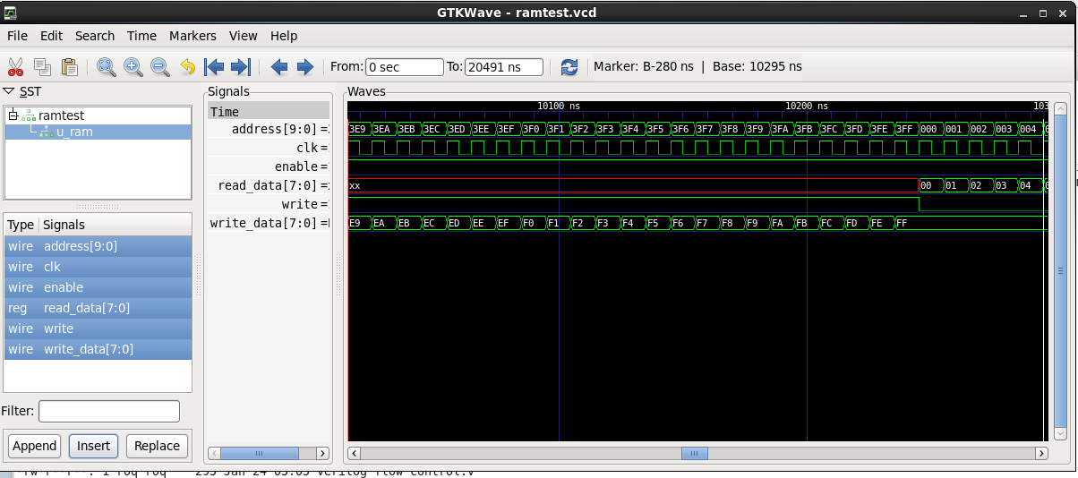
Now run the simulation, verify that the **VCD** wave file was created and
start the waveform viewer.

```
cver ramtest.v<br/>
ls ramtest.vcd<br/>
gtkwave ramtest.vcd
```

![GTKWave Verilog Viewer](gtkwave.png)
---

##@ Useful Links

* [Cliff Cummings - Verilog Papers](http://www.sunburst-design.com/papers/")
* [John Cooly - EDA Discussions](http://www.deepchip.com/")
* [Doulos - Design/Verif Languages](http://www.doulos.com/knowhow/")
* [Wilson Snyder - Veripool](http://www.veripool.org/")
* [EDA Board - Discussion Forum](http://www.edaboard.com/")
* [Design Verification Club](http://www.dvclub.org/")
* [Mentor Graphics - Verification Academy](https://verificationacademy.com/")
* [SNUG - Synopsys Users Group](https://www.synopsys.com/community/snug/snug-proceedings.html")
* [EE Times](http://eetimes.com")